Experiments
About
Reources
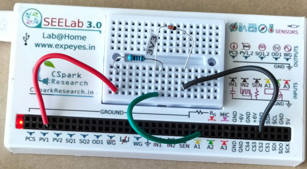
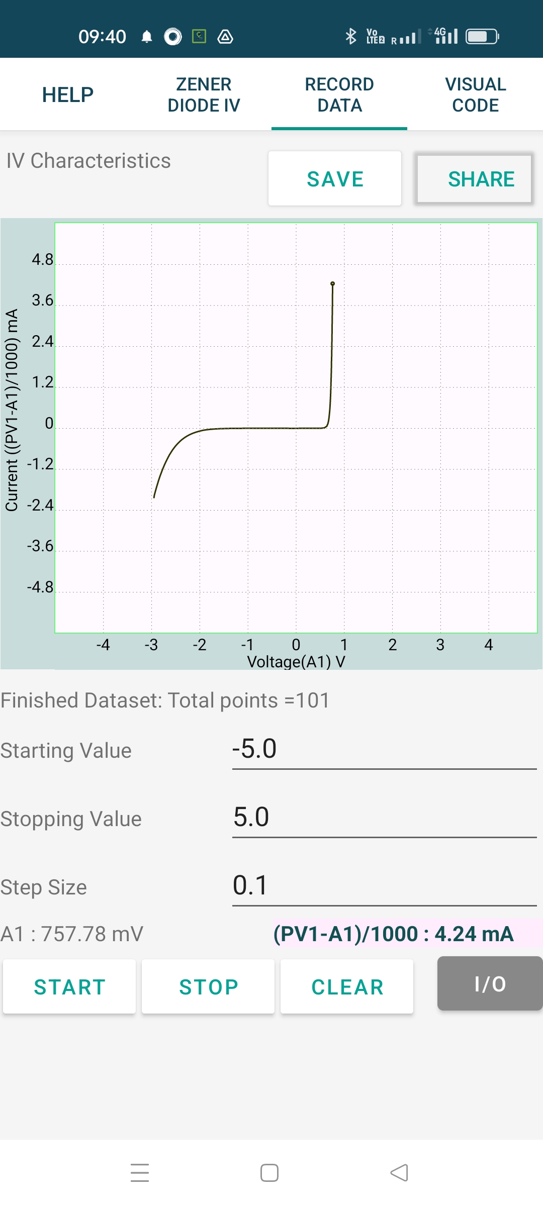
The schematic is wired as shown in the diagram below. The voltage across the diode is measured on A1. The anode of the diode is connected to PV1, through a 1k resistor. Voltage at PV1 is incremented in steps and at each point the voltage across the diode is measured. The current is calculated from i = (PV1-A1)/R. The result shown is for a 3.3 volts zener diode.

